products
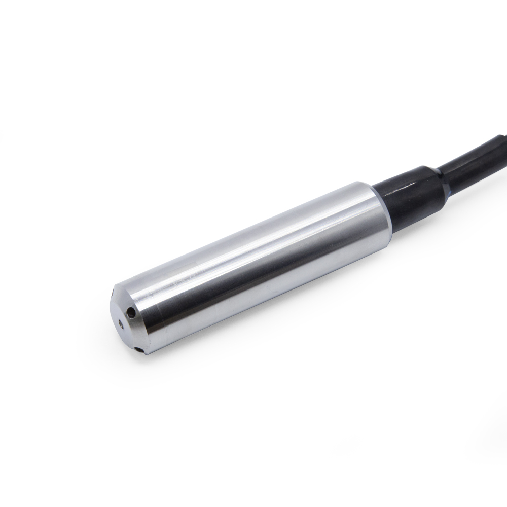
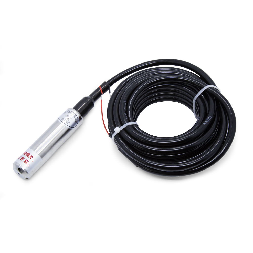
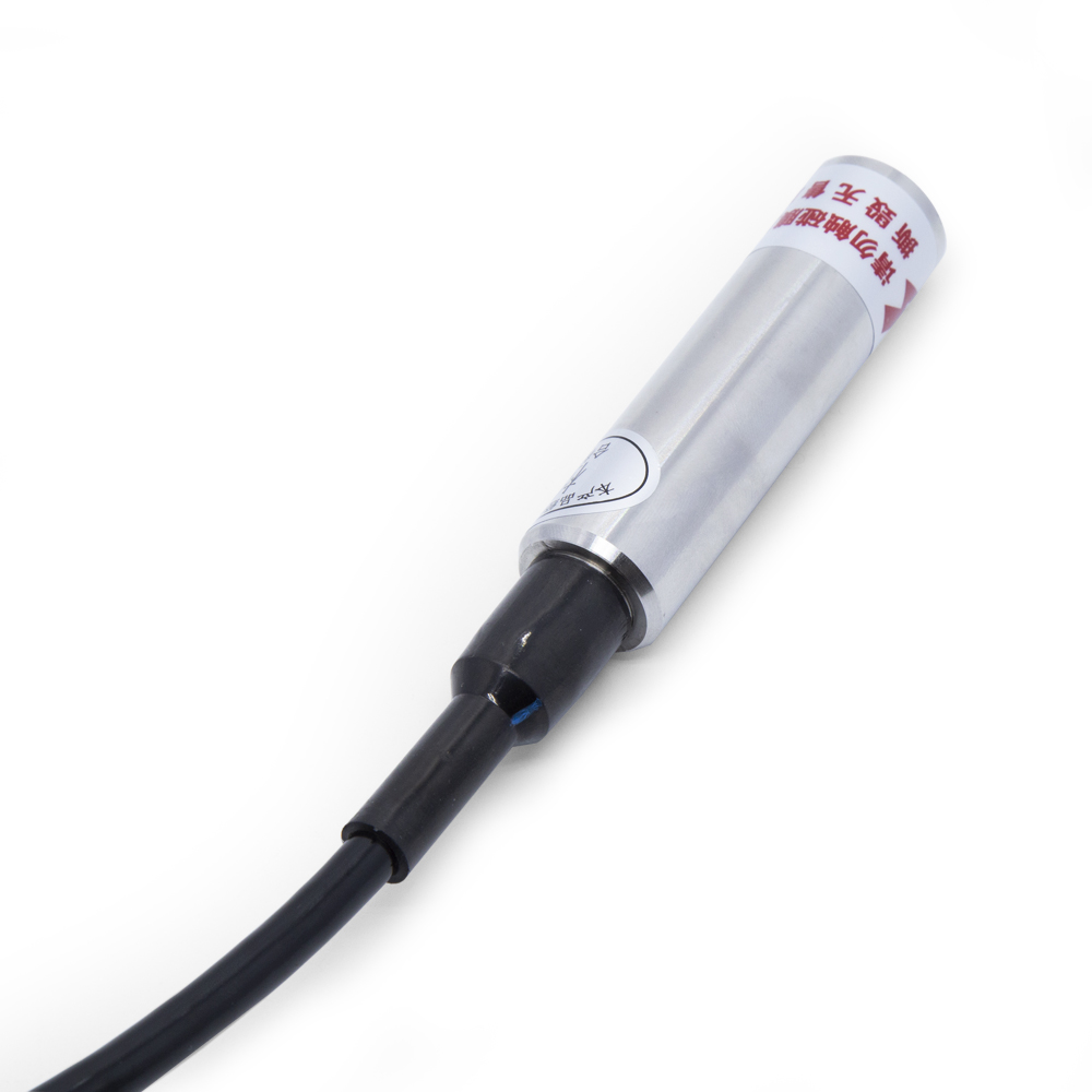
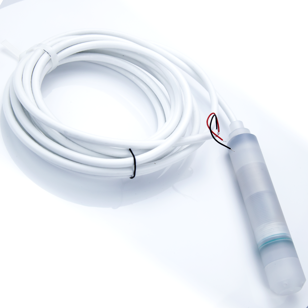
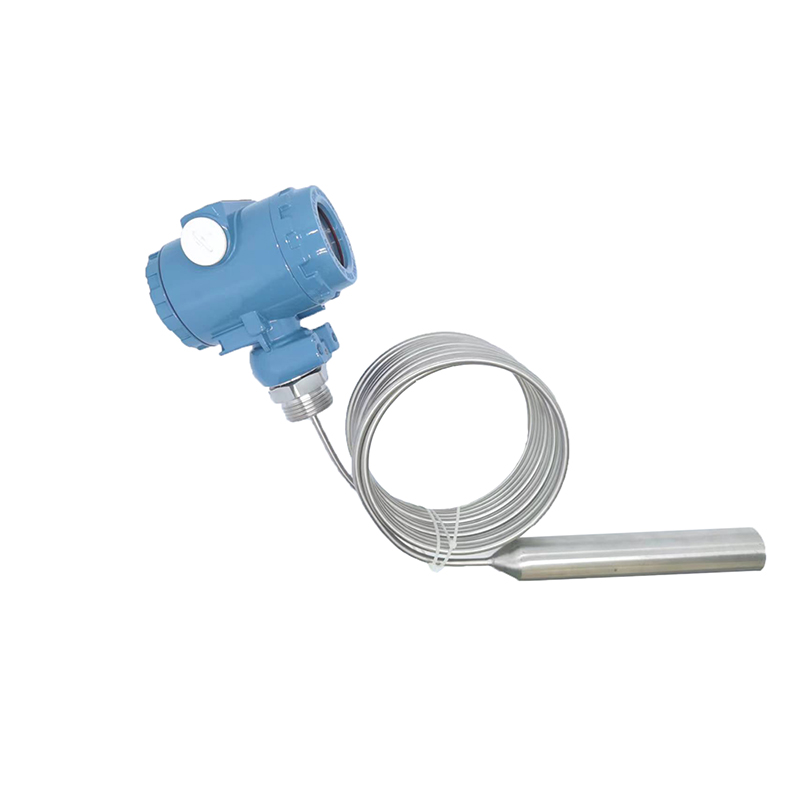
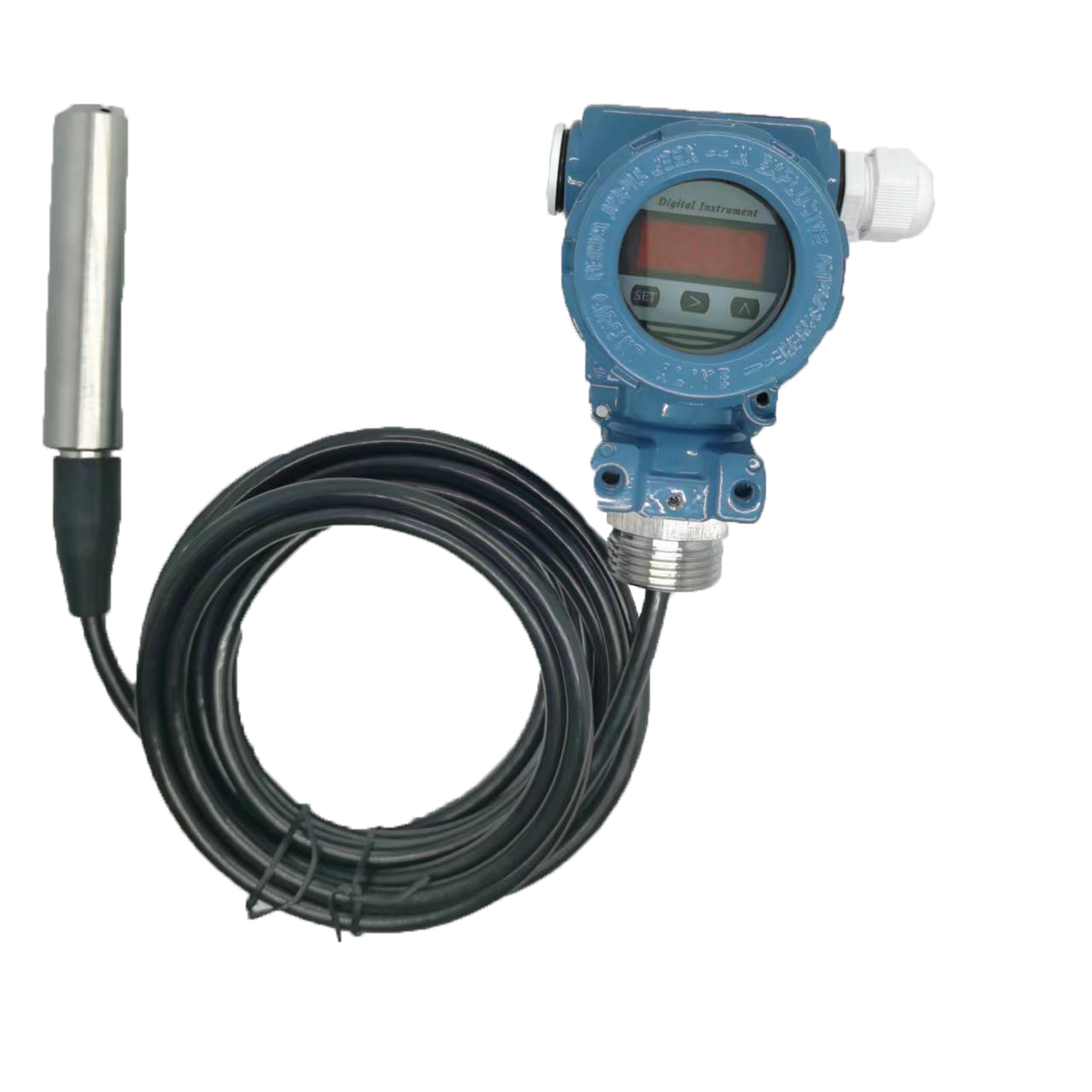
XDB500 Liquid level Pressure Transmitter
Features
● Specially used for hydrological monitoring and control.
● Compact and solid structure & no moving parts.
● Provide OEM, flexible customization.
● Fully enclosed circuit, with moisture, condensation, anti-leakage function.
● Both water and oil can be measured with high precision, which is affected by the density of the measured medium.
Application
● Industry field process liquid level detection and control.
● Navigation and Shipbuilding.
● Aviation and aircraft manufacturing.
● Energy Management System.
● Liquid level measurement and water supply system.
● Urban water supply and sewage treatment.
● Hydrological monitoring and control.
● Dam and Water Conservancy Construction.
● Food and beverage equipment.
● Chemical medical equipment.


Technical Parameters
| Measuring range | 0~100 m | Long-term stability | ≤±0.2% FS/year |
| Accuracy | ±0.5% FS | Response time | ≤3ms |
| Input voltage | DC 24V | Overload pressure | 200% FS |
| Output signal | 4-20mA(2 wire) | Load resistance | ≤ 500Ω |
| Operating temperature | -30 ~ 50 ℃ | Measuring medium | Liquid |
| Compensation temperature | -30 ~ 50 ℃ | Relative humidity | 0~95% |
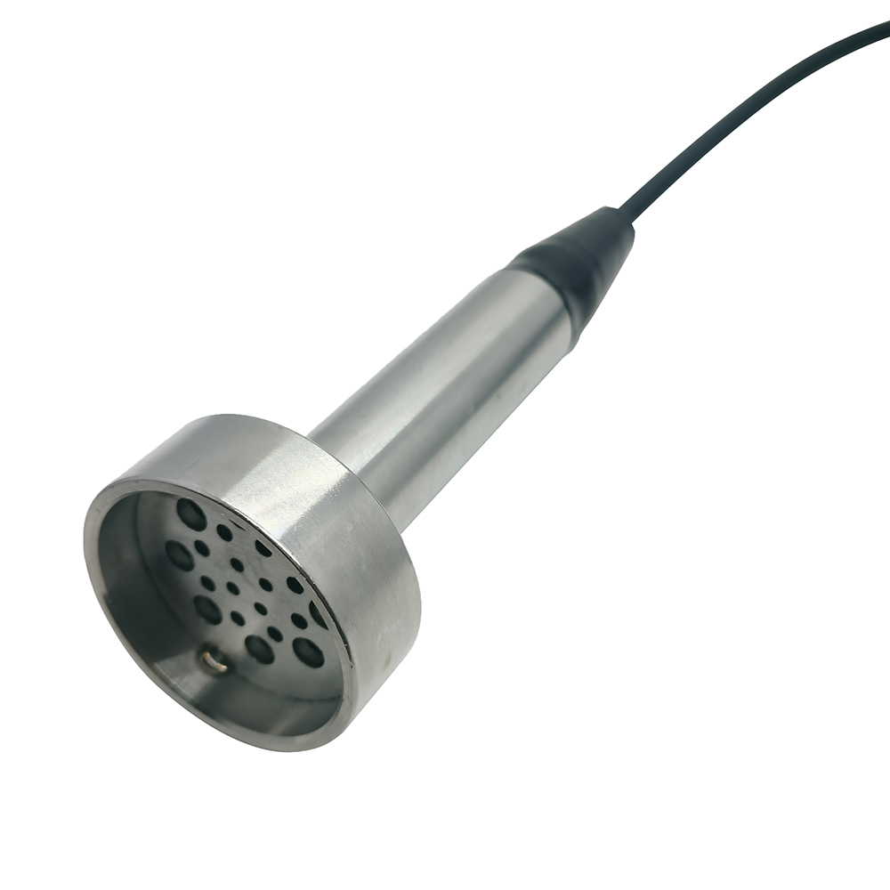
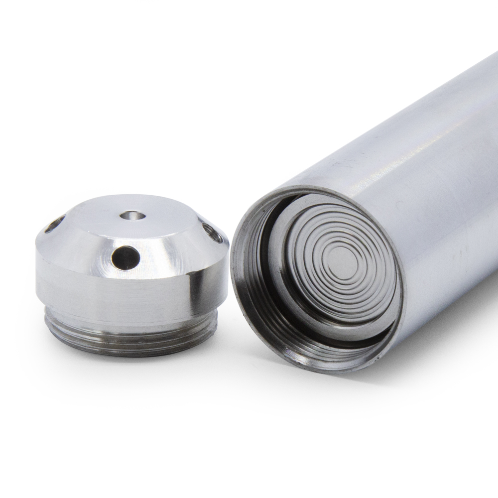
| Diaphragm material | 316L stainless steel | Cable material | Polyurethane steel wire cable |
| Housing material | 304 stainless steel | Protection class | IP68 |
Dimensions(mm) & Electrical Connection
| Integrated input | Pin | Function | Color |
| 1 | Supply + | Red | |
| 2 | Output + | Black |

Installation
When choosing a location for installation, it is important to consider the following guidelines:
● Easy Operation and Maintenance: Select a location that allows for easy access and maintenance of the transmitter.
● Vibration Source: Install the transmitter as far as possible from any sources of vibration to prevent interference with its operation.
● Heat Source: Choose a location away from heat sources to avoid exposing the transmitter to excessive temperatures.
● Compatibility of Medium: Ensure that the measuring medium is compatible with the structural material of the transmitter to prevent any chemical reactions or damage.
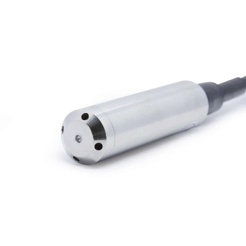
● Unobstructed Pressure Inlet: The measuring medium should not block the pressure inlet of the transmitter, allowing for proper measurement.
● Interface and Connection: Verify that the field interface matches the product interface, considering the connection method and thread type. During the connection, tighten the transmitter slowly, applying torque only to the pressure interface.
● Installation Direction: For input-type liquid level gauges, the installation direction should be vertical downwards. When used in moving water, ensure that the flow direction of the pressure sensitive surface of the transmitter is parallel to the water flow. The measuring medium must not block the pressure hole of the transmitter.
● Careful Handling: When installing the input liquid level timer, handle it gently without forcefully pulling the cable or using hard objects to squeeze the transmitter diaphragm. This is to avoid damaging the transmitter.
Ordering Information
E . g . X D B 5 0 0 - 5 M - 2 - A - b - 0 5 - W a t e r
|
1 |
Level depth | 5M |
| M(Meter) | ||
|
2 |
Supply voltage | 2 |
| 2(9~36(24)VCD) X(Others on request) | ||
|
3 |
Output signal | A |
| A(4-20mA) B(0-5V) C(0.5-4.5V) D(0-10V) F(1-5V) G( I2C ) H(RS485) X(Others on request) | ||
|
4 |
Accuracy | b |
| a(0.2% FS) b(0.5% FS) X(Others on request) | ||
|
5 |
Paired cable | 05 |
| 01(1m) 02(2m) 03(3m) 04(4m) 05(5m) 06(None) X(Others on request) | ||
|
6 |
Pressure medium | Water |
| X(Please note) | ||