products
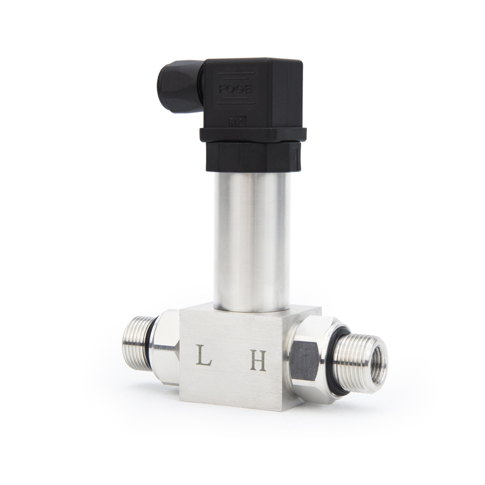
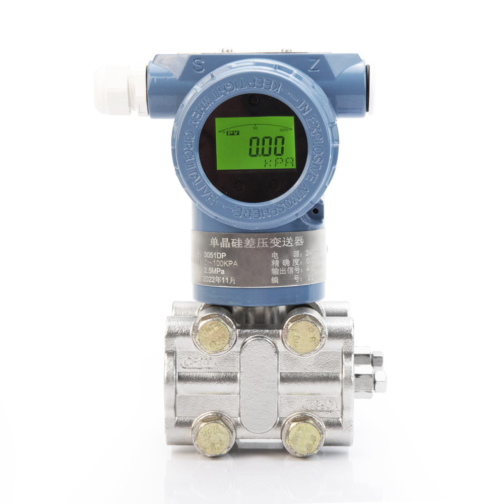
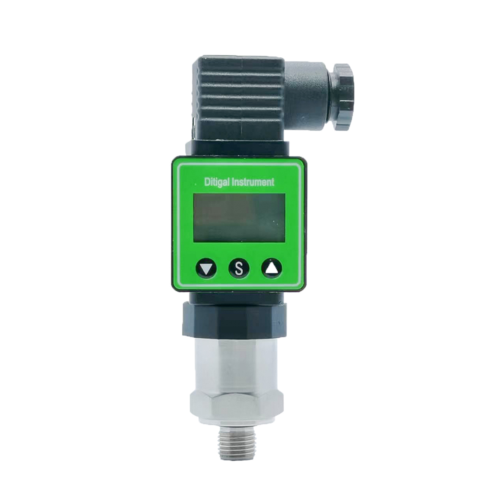
XDB603 Differential Pressure Transmitter
Features
1.316L stainless steel diaphragm structure
2.Differential pressure measurement
3.Easy to install
4.Short circuit protection and reverse polarity protection
5.Excellent shock resistance, vibration resistance and electromagnetic compatibility resistance
6.Customization available
Applications
Water supply and drainage, metallurgy, machinery, petroleum, chemical industry, power plants, light industry, food, environmental protection, defense, and scientific research etc.


Working principle
The working principle of the diffused silicon differential pressure transmitter is: the process pressure acts on the sensor, and the sensor outputs a voltage signal proportional to the pressure, and the voltage signal is converted into a 4~20mA standard signal through the amplifying circuit. Its power supply protection circuit provides excitation for the sensor, which uses a precision temperature compensation circuit. Its working principle block diagram is as follows:
The working principle of the diffused silicon differential pressure transmitter is as follows: The process pressure acts on the sensor, which generates a voltage signal proportional to the pressure as output. This voltage signal is converted into a 4-20mA standard signal through an amplification circuit. The power supply protection circuit provides excitation to the sensor, which incorporates a precision temperature compensation circuit. The functional block diagram is shown below:

Technical Parameters
| Measuring range | 0-2.5MPa |
| Accuracy | 0.5%F.S |
| Supply voltage | 12-36VDC |
| Output signal | 4~20mA |
| Long-term stability | ≤±0.2%F.S/year |
| Overload pressure | ±300%FS |
| Working temperature | -20~80℃ |
| Thread | M20*1.5, G1/4 female, 1/4NPT |
| Insulation resistance | 100MΩ/250VDC |
| Protection | IP65 |
| Material | SS304 |
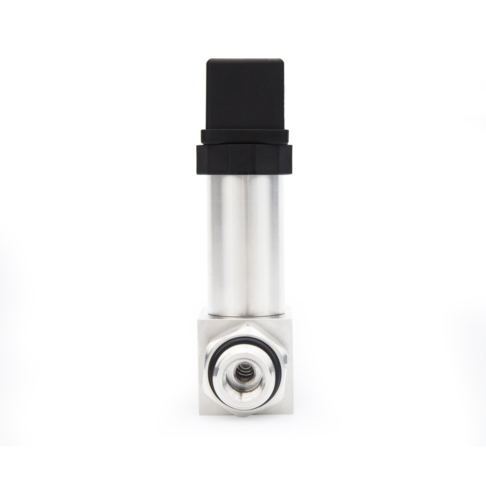
Dimensions(mm) & Electrical Connection

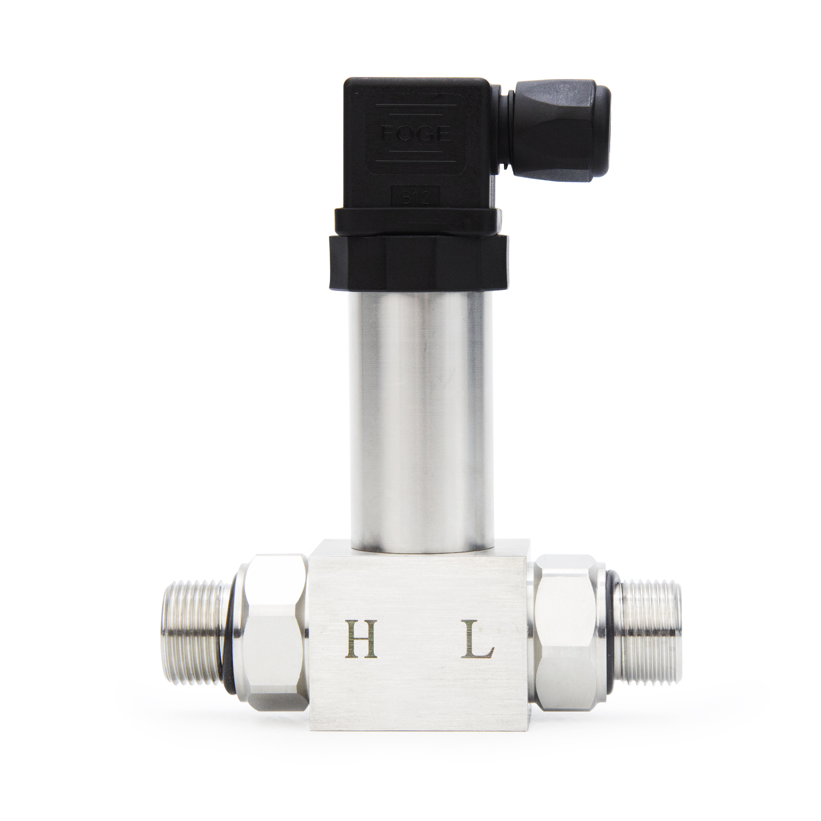
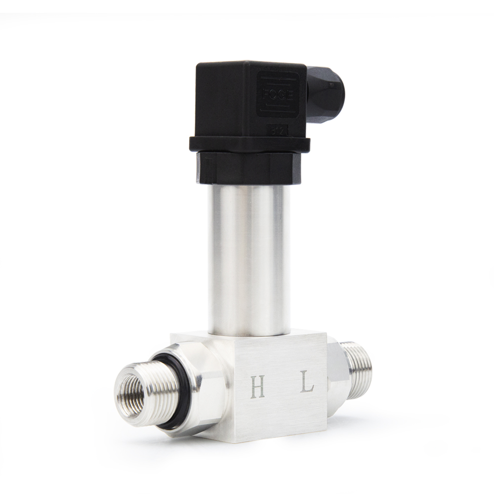
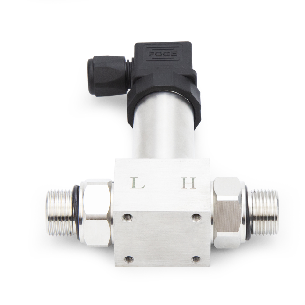
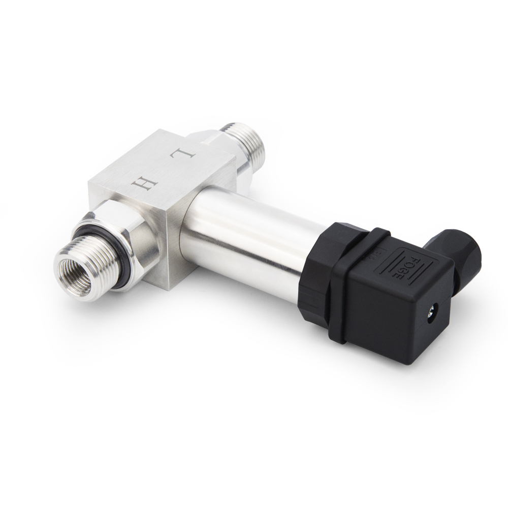
Pressure connector
The differential pressure transmitter has two air inlets, one high-pressure air inlet, marked "H"; one low-pressure air inlet, marked "L". During the installation process, air leakage is not allowed, and the existence of air leakage will reduce the measurement accuracy. The pressure port generally uses G1/4 internal thread and 1/4NPT external thread. The simultaneous pressure applied to both ends during static pressure testing should be ≤2.8MPa, and during overload, the pressure on the high-pressure side should be ≤3×F.S.
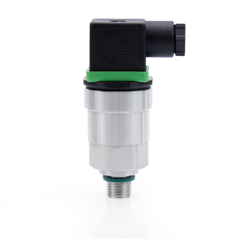
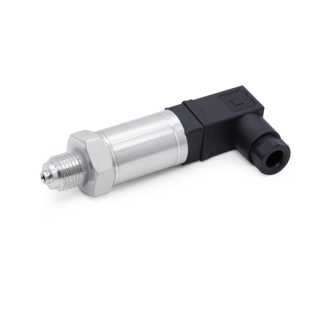
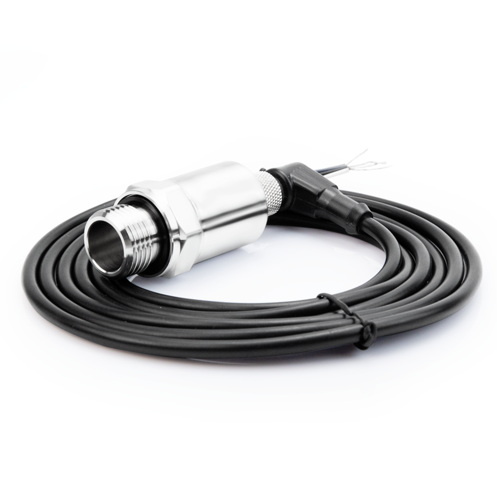
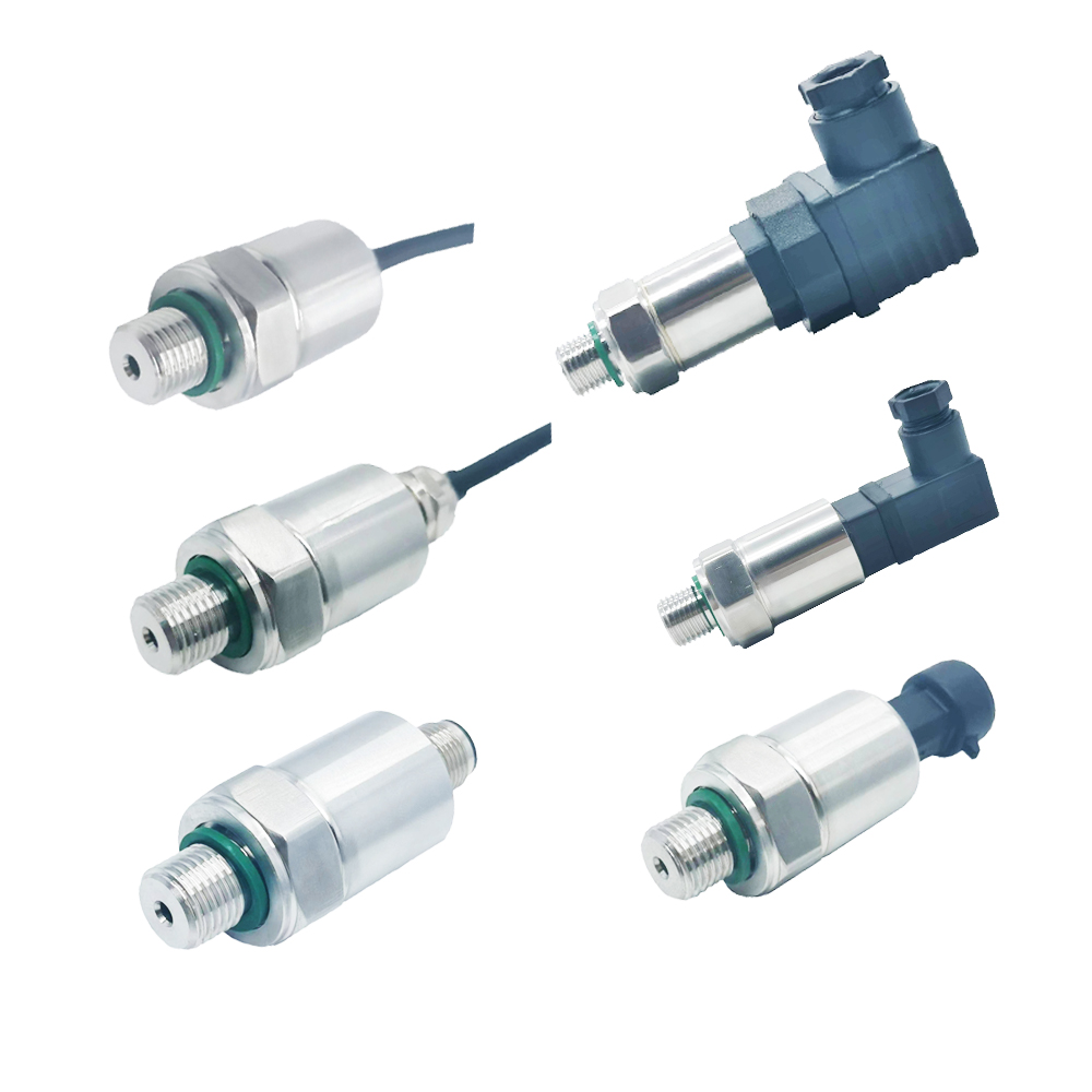
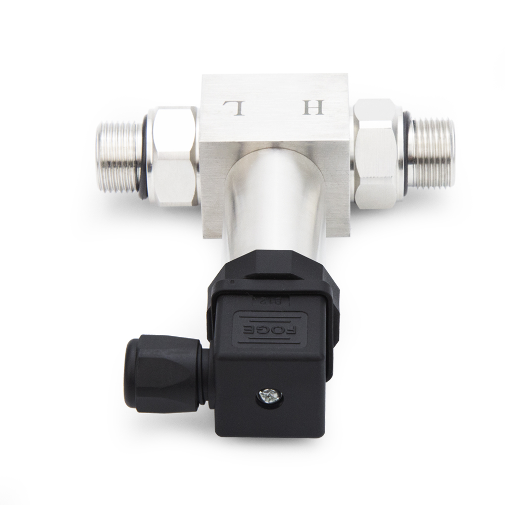
Electrical connector

The output signal of differential pressure transmitter is 4~20mA, range of supply voltage is(12~ 36)VDC,standard voltage is 24VDC
Ordering Information
How to use:
a: The differential pressure transmitter is small in size and light in weight. It can be installed directly on the measurement point during installation. Pay attention to check the tightness of the pressure interface to prevent the measurement accuracy from being affected by air leakage.
b: Connect the wires according to the regulations, and the transmitter can enter the working state. When the measurement accuracy is high, the instrument should be powered on for half an hour before entering the working state.
Maintenance:
a: Transmitter in normal use requires no maintenance
b: Transmitter calibration method: When the pressure is zero, first adjust the zero point, and then re-pressurize to full scale, then calibrate the full scale, and repeat until the standard requirements are met.
c: The regular calibration of the instrument should be operated by professionals to avoid man-made damage
d: When the instrument is not in use, it should be stored in a clean environment with a temperature of 10-30℃ and a humidity of 30%-80%.
Notes:
a: It is recommended to add a two-way valve when installing the differential pressure transmitter to prevent excessive static pressure from both ends of the transmitter
b: The differential pressure transmitter should be used in gases and liquids that do not corrode the 316L stainless steel diaphragm。
c: When wiring, strictly follow the wiring method in the manual to ensure the normal operation of the transmitter
d: Shielded cables can be used in occasions where the on-site interference is large or the requirements are high.